Building a mechanical keyboard
A while ago, the household got a mechanical keyboard. I tried it out, and immediately knew I needed a proper keeb. Fast forward a few months, and I’m building my own, actually soldering parts together.
How it all started •
After I tried the mech board at home, I fell in love with the feeling and got myself a lovely Vortex Race 3 for the office. It looks, um, like a mechanical keyboard, so it gets comments ranging from “OMG your keyboard is so cool”, to “oh I used to have an old keyboard like that at home”, so yes, it gets noticed.
It’s also lovely to type on, super quiet compared to what I had expected (Cherry MX brown switches are absolutely office-compatible). It has built-in mac & linux support, colemak and dvorak layouts, plus three fully programmable layers, too, so I can map my own key combinations (arrows on the home row etc.)
Fast forward a few more months, having spent a week working from bed on a macbook due to a bad cold, I got repetitive strain injury (mostly due to bad posture and hand positioning). So partly due to that, partly because why stop at one keyboard, I started looking into split keyboards.
Why a split keyboard? •
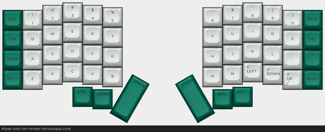
Well, if you put down your hands in front of you, you will notice they sit in an angle rather than parallel to each other. Also, if you lay your hands flat on a keyboard, you will notice that your fingers don’t all rest in the exact same vertical position. This brings us to my chosen keyboard, the keeb.io Iris, which looks something like this:
Keyboard anatomy 101 •
Most mechanical keyboards consist of a PCB (or two, if it’s a split like the Iris — PCB stands for printed circuit board), a case to protect it, key switches, most of the times a plate to hold the switches in place, and keycaps to cover the switches and make typing comfortable.
They also feature a microcontroller, such as an Arduino-compatible Pro Micro, which make it possible for the board to register key presses and send them to the computer, and enables full custom programmability (not just Vortex Race-like, but really, really full.) There’s a lot more bits and bobs that are needed for the build; we’ll get to that.
Split boards have a master and a slave side; the master is connected to the computer, and the two boards are connected with a TRRS jack cable. However, a pro micro is needed on the slave side as well, to enable the two sides to communicate.
Preparations •
Getting parts
I stupidly waited until my go-to EU supplier CandyKeys ran out of Iris kits, so I had to order directly from Keeb.io in the US. Dealing with customs clearance, shipping costs, documentation and paying a high VAT[1] is not much fun, but whatever. Order from within your customs borders, whenever you can.
My kit includes 2 PCBs (for the two sides), with diodes for each switch, TRRS jack sockets, a reset button, a couple of resistors, and two pro micros (the master side with USB-C, which is considered to be more reliable on the long run, meaning it doesn’t break off).
I also got 56 Cherry MX Brown switches (AliExpress is a great source for getting these), clear acrylic plates, the necessary cables (a TRRS jack, NOT the same as the ones used for audio!)[2], and some fancy keycaps (that haven’t shipped yet).
Software
Most custom and DIY boards use the QMK Firmware. It already has layouts for most available boards, including the Iris. Before I start soldering, I wanted to have a look at the software side of things to see what I’m up against. Following QMK’s Complete Newbs Guide, I installed the QMK toolbox, played around with it for a while, it seems very straightforward.
Tools
Building a keyboard usually means a lot of soldering[3]. For those unfamiliar with soldering: the goal is to connect two pieces of metal so they conduct electricity (so that, for instance, a pressed key switch can send a signal all the way to the microcontroller, through the PCB’s circuits). This is done by melting another metal to connect the two. Melting is done by a soldering iron, and the connecting metal is tin and lead solder with a low melting point (around 200℃, but the iron melts it to a higher temperature, to be sure).
A minimal soldering setup has to include:
- Soldering iron (I’m using a Weller)
- Rosin-core solder (around 0.8mm diameter is best for this purpose; mine was 1mm. It usually comes as a reeled wire, and is much heavier than I thought. A 40% lead, 60% tin content is ideal for this purpose.)
- Flush cutter (for cutting diode legs etc.)
In addition, it’s good to have:
- Multimeter (to measure conductivity)
- Tweezers or long nose pliers (to hold small things in place)
- Flux (to make solder stick better)
- Solder sucker or wick (for corrections — actual desoldering is best done with a proper desoldering iron)
The build •
It would be exaggerating to say this was the first time I held a soldering iron, but I was definitely not confident. I got a crash course from someone more experienced[4], desoldered and soldered 4-5 diodes on an old circuit board that had no use, and was good to go. I mosty followed the excellent and detailed build guide on keeb.io. This is how it’s done, and my experience with it.
One really important thing to note is that the two halves have to be symmetrical, so I had to solder on the other side of the other half. Otherwise, I’d end up with two left or two right halves.
1. Soldering the diodes
First, the diodes had to be separated from the paper strip holding them neatly together, then bending the legs with a plier. I also tested each of them with a multimeter before soldering anything. If one of them is faulty, better not to solder it in and realise afterwards.
The only tricky thing with diodes is to insert them in the correct orientation[5]. After every four or five, I tested them with a multimeter, to see if they were soldered in correctly. I had 56 diodes to solder, that meant 112 soldering points. I think I got quite good at soldering by the end.
2. Soldering the resistors
Resistors are not orientation-sensitive, and only two of them are needed. So this was an easy step.
3. Soldering the TRRS jacks and the reset switches, one on each side.
Nothing special.
After this step, there’s a bunch of optional steps that I skipped, as LED backlighting does nothing for me (for now).
4. Soldering the Pro Micro header pins
Only the header pins for now. We have to make sure they are vertical, as in as close to 90° as possible, and the two rows of pins are parallell to each other. I start by soldering a few pins on each side first, and try on the pro micro to see if it fits. If not, adjust; then solder the rest. The pro micros themselves should NOT be soldered yet.
5. Soldering the switches

This is a very fun part, finally our keyboard will start to look like one! To avoid soldering a faulty switch, I test each of them with a multimeter[6]. Now, the switches have to be popped into the top plate (easy to identify — this is the one with square holes in it), pushed together with the PCB (facing the non-soldered side) and soldered into place. Following common recommendation, I first soldered in the switches in the corners to make sure everything is tight and well aligned, and added the rest of them after.
It’s important here to make sure that the switches sit tightly in the plate, and fit the PCB as snug as possible. When this is done, there should be no vertical space for the switches to move within the plate[7].
6. Flashing the pro micros
This step should be done before soldering them, because desoldering is a pain if it turns out that the pro micro is faulty.
As a reminder, we need two of them; one for each side. Only one of them will be connected to the computer though, and I chose a USB-C version for that, the Elite-C, because they are less prone to breaking off. The standard, cheaper version is fine for the slave side.
Pro micros are sensitive pieces of equipment, so I made sure I was not charged before handling them. I did this by simply touching the bare metal parts of a radiator.
To flash the pro micro (meaning, format it and install a keyboard controller), first I open the QMK toolbox on my computer, then connect the pro micro, and put it in reset mode. This is achieved by shorting GND and RST with a pair of tweezers or a piece of wire (while the pro micro is connected). Now, QMK toolbox should recognise the pro micro.[8] Flashing itself is best done from the command line — I tried using the QMK toolbox GUI, but that didn’t work properly for me. The magic command is:
make iris/rev2:default:dfu for the Elite-C, and make iris/rev2:default:avrdude for the standard pro micro.
After this step, when the pro micro is unplugged and connected again, it should show up as a keyboard — even though it’s not built into one yet!
7. Soldering the pro micros
One thing to keep in mind is that the pro micro on the master side is facing down (the side with the components to the PCB), and the one on the slave side facing up. And, practically, the USB connector towards the edge of the keyboard.
I was very careful at this step, because the header pins are very close to each other, so there’s not much space, and the pro micro is a sensitive piece. I didn’t want to accidentally fry any of its tiny components with the soldering iron.
8. Putting it all together: bottom plate and keycaps

Now the easy and fun part, I put on the bottom plate using the standoffs and screws that came with the plates. They came with 10mm standoffs, which I found a bit too short, so I ordered some tiny nylon washers from RS Online, until the 12mm standoffs get here from AliExpress.
The initial keycaps were cheap TaiHao caps, because they shipped fast (and because I had a hard time choosing the final ones). Now the keeb is sporting EnjoyPBT Black on Whites from Kbdfans.
.")
Building a keyboard was a real fun day and a half, and I’m already looking forward to my next build, probably a second Iris, for the home office.
Second poor decision: I ordered the board to Hungary, where VAT is 27%, as opposed to 20% in the UK. ↩︎
The only f*$%up in my build was getting the absolutely wrong cable to connect the two halves. Luckily, even in my small hometown, a computer accessories store had the right thing in stock. ↩︎
Unless it’s hotswappable, meaning you can put tiny metal tubes (hotswap sockets) into the holes in the PCB where you would solder the switches etc. otherwise, so you just pop in the sockets and the switches and you’re ready to go. This only works on PCBs that already have diodes soldered on. ↩︎
Thanks, dad. If your dad is not the kickass solderer mine is, you can get the same results by searching “how to solder” on YouTube. ↩︎
On the Iris PCB, it’s easy: black end to the square hole, other end to the round hole. ↩︎
Like many things in the build, this would be much easier done with three hands instead of two: two to hold each leg and each multimeter probe end together, and a third to press the switch to test. ↩︎
I learned this the hard way and had to adjust a few switches after the whole thing was soldered. At least I learned some fixing, too! I didn’t have to fully desolder these switches, just heat the tin around the switch legs enough to melt it and be able to push the switch a bit further in. Btw, I totally forgot to solder one switch properly back in, so I have one switch that is connected by mere coincidence, which I should fix ASAP. ↩︎
See more on flashing the Iris here: Flashing Firmware - Keebio Documentation ↩︎